Aerospace Structures
- Intro to Structural Analysis
- Stress
- Shear and Normal stress produce fundamentally different forces in the material
- What is strain? What are the units of strain?
- What is normal strain? What is shear strain?
- What is a positive and negative normal strain?
- What is a positive and negative shear strain?
- Normal Strain is?
- Shear Strain is?
- Poisson’s ratio?
- Hooke’s Law?
- Plane (2D) Problems
- Beams and Plates
- 2D State of Stress
- Aircraft Materials
- Static Equivalence
- Partial Derivative
- Support Conditions
- Internal Loads
- Force and Moment Diagrams
- Euler Buckling
- Inelastic Buckling
- Plate and Local Buckling
- Bending
- Thin Wall Assumptions
- Shear
Intro to Structural Analysis
Content Tags: Hookes Law, Internal Loads, Strain, Stress, Supports Created: March 6, 2022 9:10 AM
Stress
- Stress on a small element of a material under load
- 2 types of stresses:
- Normal
- Shear
- Ask what does a load do to a cross section?
- What loads are there? Moments? Stresses?
Shear and Normal stress produce fundamentally different forces in the material
- Normal is a compressive or stretching action
- Shear is considered as though it acts on a plane
What is strain? What are the units of strain?
- Strain is a change in material distortion under the effect of a stress
- The units are dimensionless (Change in Length/Length)
What is normal strain? What is shear strain?
- Normal strain acts through the cross section of the body to lengthen or contract it
- Shear strain creates torsion and warping
What is a positive and negative normal strain?
- Positive normal acts in torsion
- Negative acts to compress
What is a positive and negative shear strain?
- Positive and negative only alters the direction of the torsion. So clockwise or counter-clockwise
Normal Strain is?
- The slope of displacement
Shear Strain is?
- Still non-dimensional
- Relationship??
Poisson’s ratio?
- Ratio of strains. Reaction strain acting in orthogonal direction is cause by original strain.
Hooke’s Law?
- Constant Value = Stress/Strain, while elastic.
Plane (2D) Problems
- Disregard a particular aspect because nothing important is happening in the other access out of plane. This needs to be carefully evaluated.
Beams and Plates
- Take a beam and extrude it for plates
- Plates have a poisson effect that beams don’t have
2D State of Stress
- Your stresses are dependant on your coordinate system
- Can resolve state of stress into principal stress
- Use Moores circle
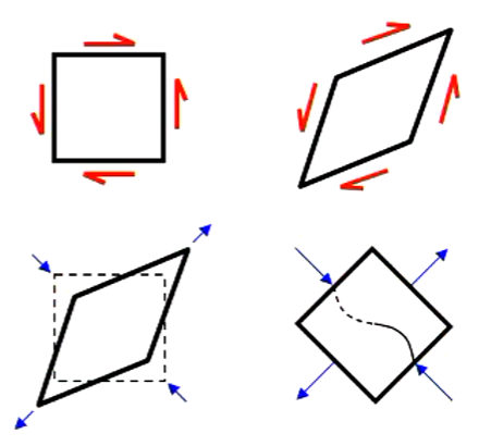
- A cylinder under normal tension will fracture vertically
- A cylinder under shear will fracture diagonally. Imagine the shear diagram deforming a square into a kite shape.
Aircraft Materials
- Common Materials:
- Metals (Most discussed)
- composites
- Sandwich
Static Equivalence
- Same forces and same moments
- Internal loads must be equivalent to the external load that is acting on the body.
- Internal reaction loads are equal and opposite. The internal loads are not.
Partial Derivative
- The partial derivative is the derivative of a function with respect to one variable only
- This gives the rate of change, or slope, of a function with respect to one variable
Support Conditions
- Import drawings for supports. (Roller, Fixed, Pin). Add degree of freedom info.
- Rollers always provide a force in the Y direction regardless of the sign of the force. Not in the X direction. Or vice versa depending on the unit system.
Internal Loads
- 4 Types of internal loads:
- Normal (N)
- Shear (V)
- Torsional (T)
- Bending (M)
Force and Moment Diagrams
- Take a slice and determine the shear force and moment at that point (This is important for this course)
Reference Material
(1A)_Intro_to_structural_analysis-1.pdf
Euler Buckling
Created: April 28, 2022 11:02 AM
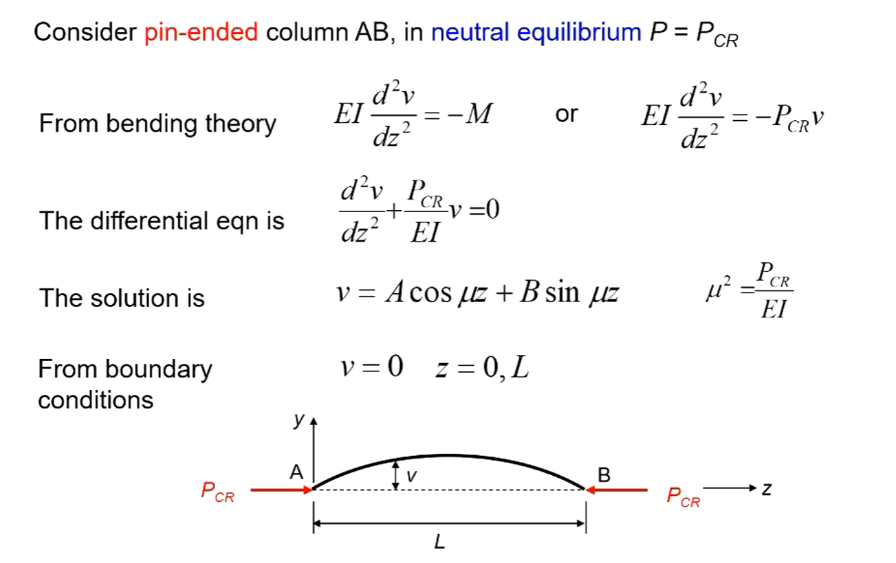
Euler Column Theory
- Valid, within the limits of assumptions
- Based on a perfect stable section column
- The column is perfectly straight
- Load is applied at the section centroid
- Column material is homogenous
- Stresses are in the elastic range
- No local section instabilities (no twist or deformation)
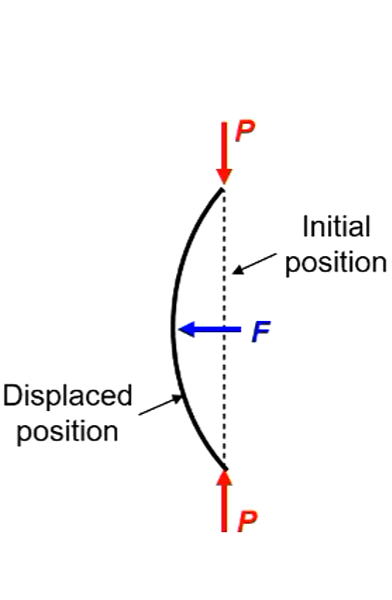
- Perfect column under compressive load P
- Load associated with buckling is $P_{CR}$
- If column is displaced by lateral load F
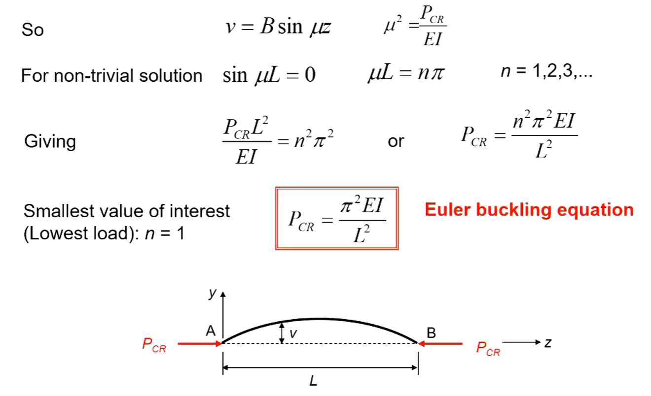
Derivation of Euler Buckling Equation
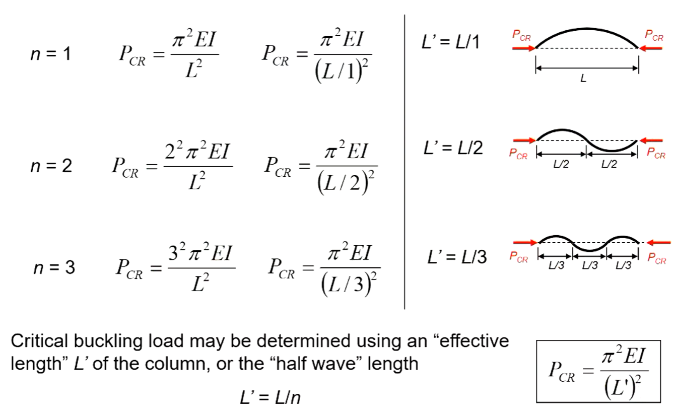
Buckling Modes
- Each n buckling mode (displacement shape) has an associated buckling load
- n = number of “half waves” in buckling mode shape
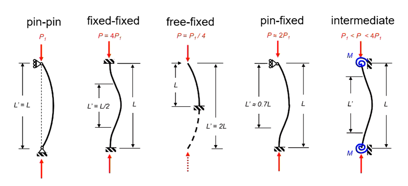
Effective Length
End Fixity
- How the ends of the columns are restrained
- Most columns have some form of restraint (end fixity)
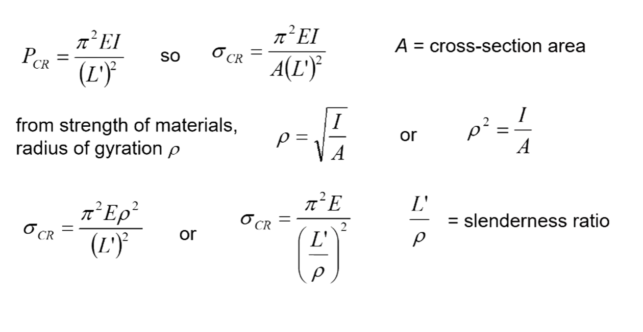
- To account for this, the effective length L’ is adopted $P_{CR} = {\pi^2EI\over (L’)^2}$
Second Moment of Area
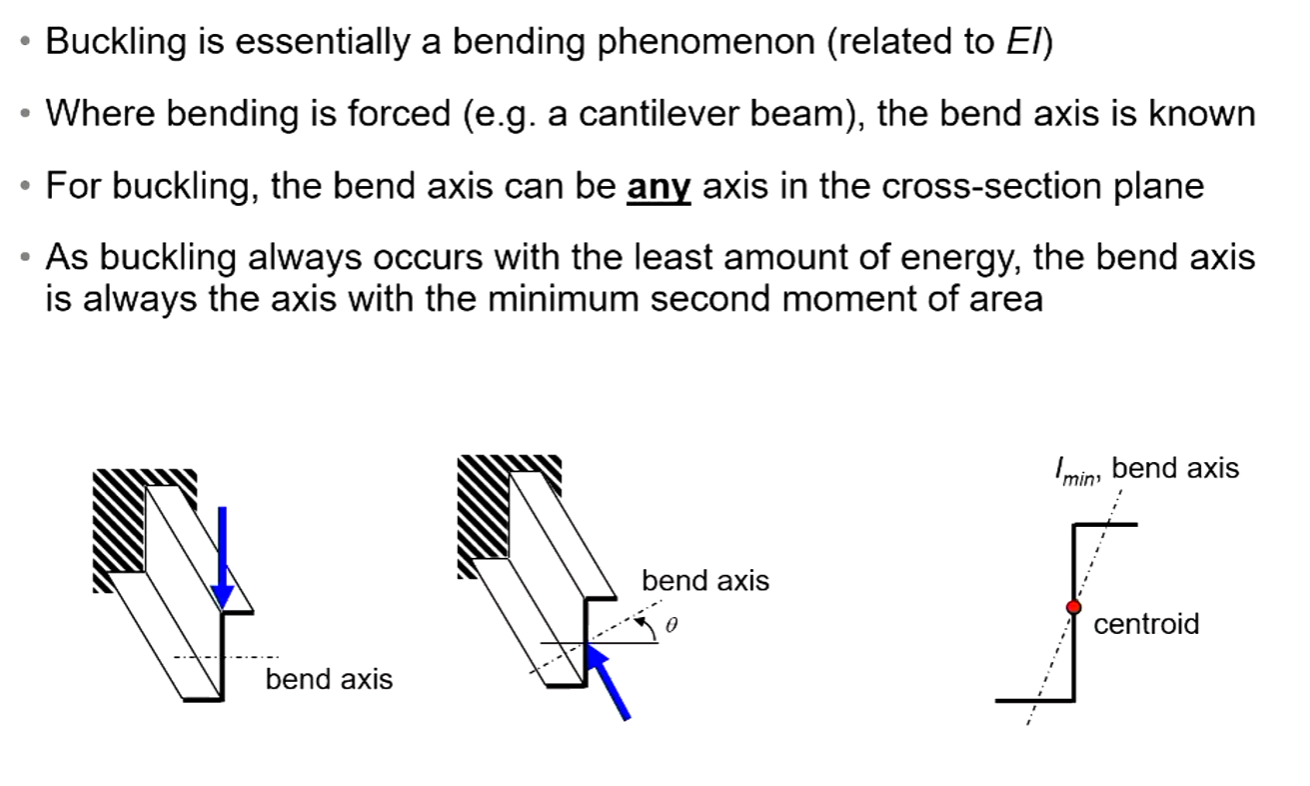
- Buckling always occurs around the axis of $I_{min}$
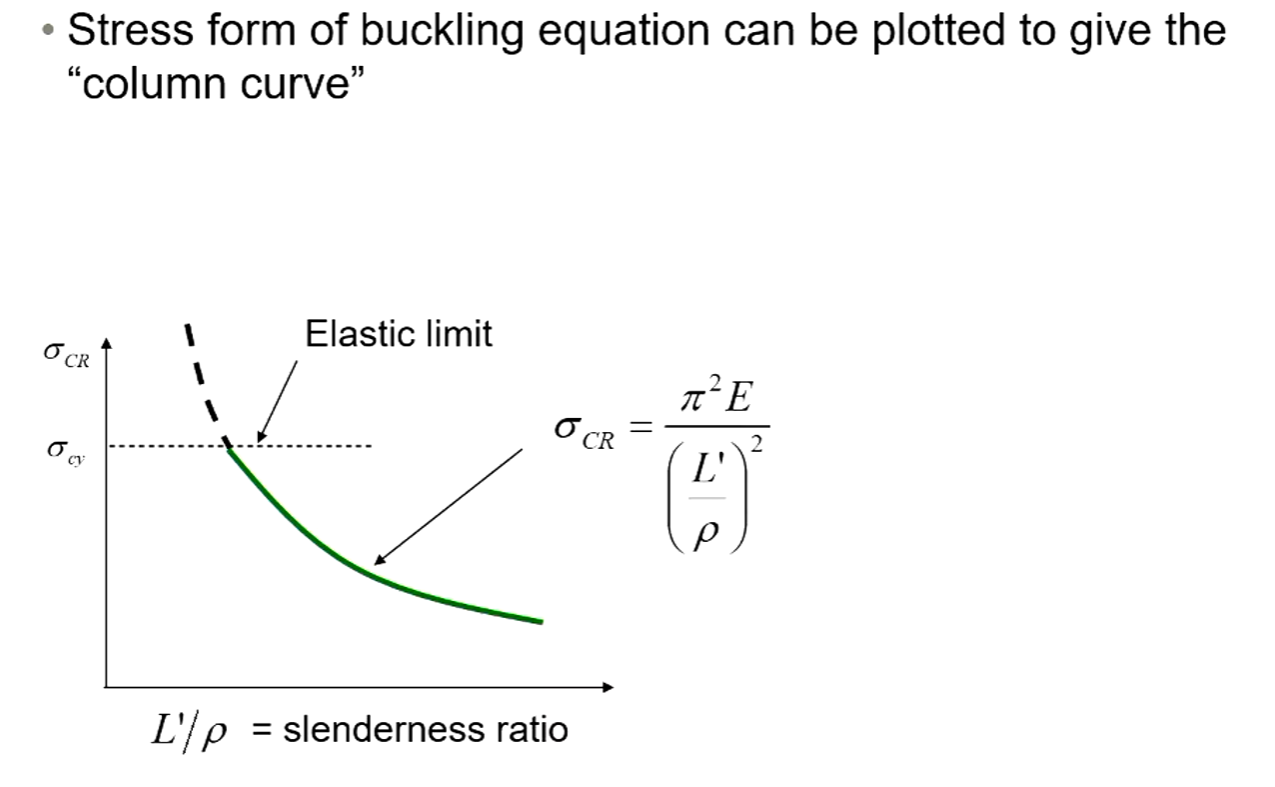
Stress Form of Buckling Equation
Column Curve
Inelastic Buckling
Column Curve Ranges
- Metal material behaviour is non-linear following yield or elastic limit
- “Long” columns buckle when material is still in elastic region
- “Short” columns undergo plasticity before buckling
- Euler theory will over-estimate the buckling stress in the case of a “short” column
- Very short columns (L’/$\rho$ ~ 10) fail by crushing, or “block compression”
Empirical Short Column Equations
- Empirical (test-based) relationships developed for buckling of thin-walled sections (which incorporates local buckling)
- Column curve is a structural response (not material)
- Empirical relationships developed for common sections and materials
- Linear and parabolic forms most common, other indices are possible.
- Linear:
- Parabolic:
- Stress $\sigma_{c0}$ is a property of the cross-section (assumed independent of length), and material
- Can be found using several approaches
- Assumed equal to ultimate compressive strength $\sigma_{cu}$
- Taken from test data for a very short column
- Determined analytically or semi-empirically
- Found using data sheets (e.g. ESDU), standards (e.g. MIL-HDBK), etc
Euler-Johnson Equation
- A type of parabolic short column equation
Inelastic Plate Buckling
- Elastic-plastic behaviour for metals affects buckling
- Similar behaviour previously seen for columns
- Buckling can occur at stresses above elastic limit
- Less common as requires thick plates
- One approach (less common in industry) treats the plate as a column
- Relate the plate to an equivalant column using:
- Then simply use the above inelastic equation depending on the situation (Linear, Parabolic, Euler-Johnson)
Plate and Local Buckling
Flexural Buckling
- Global Buckling
- Primary instability mode of the entire column, or instability due to overall column bending
- Characteristic length ~ distance between supports
- Primary instability mode of the entire column, or instability due to overall column bending
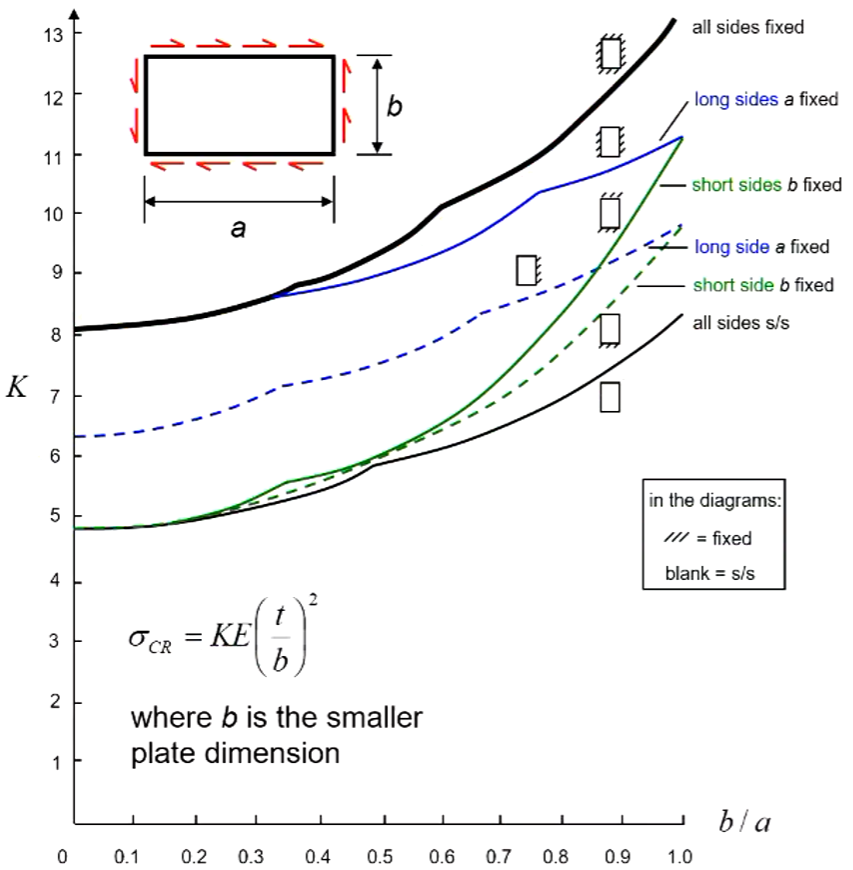
Rectangular Plates in Shear
- Buckling in shear is determined from the same equation
- Analytical derivation of buckling not considered here
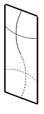
- A rectangular plate in shear develops a series of closely space buckling waves at approximately 45 degrees
- The effect of boundary conditions and plate size is similar to that of a plate in compression.
- We use a different graph to obtain our K values but the process is the same from a calculation standpoint.
- In shear buckling the b in the equation is always the smaller dimension
- $\sigma_{cr} = {KE ({t \over b})^2}$
Rectangular Plates in Compression
- With plates we need to more carefully consider which mode of buckling will be take the least amount of energy.
- Across the width of the plate mode 1 is still the lowest so only one half wave will be present
- This is not true when considering the height.
- The plates will buckle into a shape that is the closest to maintaining “square” buckles along its length. So each buckle will occur at lengths that approximate square sections of the total plate.
- As seen above the plate buckles into two “square” sections. This is the lowest energy buckling mode.
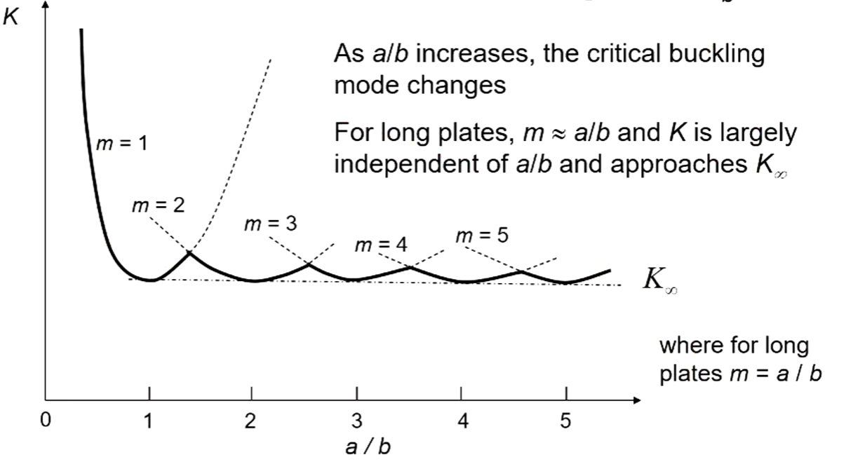
- $K_{\infty}$ is a good approximate for really skinny plates.
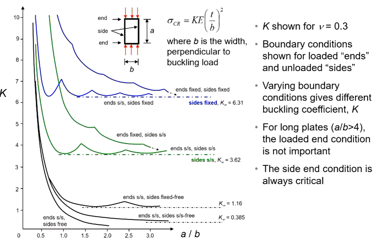
Plate Buckling Stress
- Compression and shear stresses on a plate can lead to buckling
- Buckling load of a flat plate is dependant on
- Type of loading (compression, shear)
- Material (E, v, t)
- Edge support (fix, pin, etc)
- Geometry of the plate (dimensions, aspect ratio)
- Buckling stress of plates is always:
Where,
- K is a buckling constant
- Varies with restraint, geometry, loading, material
- E is elastic Modulus
- $({t\over b})$ is the ratio of the plate thickness to width.
- b is always the width of the loaded edge regardless of orientation for compression buckling
Local Buckling
- Occurs when the column acts like a collection of square plates. Common in thin-walled structures.
- Thin-wall panels can buckle before or after flexural buckling
- Usually confined to localised portions of the total length
- Characteristic length ~ cross-section dimensions
- Thin-wall columns see local buckling of the flanges
- Stiffened beams see skins buckling between stiffeners
- Simple predictions for local buckling can be made by analysing the structure as a series of plates
- The corners of a cross-section and the stiffeners in a stiffened beam provide restraint
- Each segment or plate has different geometry and boundary conditions and requires separate calculation
- The restraint applied on each plate by the corners and stiffeners is difficult to determine
- In both cases the restraint should vary between a fixed and simple support
- Simple support can be assumed for conservative estimates unless the condition is known or given
Bending
Bending Stresses
- Bending of a beam causes compression and tension stresses on a cross-section (bending stresses)
- These are direct stresses, normal to the cross-section
- Between the compression and tension regions is a line of zero bending stesses, called the neutral axis
- The neutral axis passes through the section centroids
- The neutral axis has no deformation or stains associated with bending stress
- Bending of a beam can occur around two axes
- The two in-plane axes of a cross-section
- bend axes, moment, stress distribution, resists all change
Symmetric Bending
- Symmetric Bending occurs for bending of beams with one or two axes of symmetry
- Axis of symmetry = “mirror plane”
- Bending behaviour is simplified as bending around the two axes acts independently
- Uses equation: $\sigma {bending} = {M{bending} \over I_x} y$
- For bending in two seperate axis we can calculate the stress for both and simply add them. Direct stress can also be added.
Asymmetric Bending Equation
- Bending always relates to a centroid coordinate system
- General equation for bending stress:
Works for any bending problem. Including symmetric bending and single moment bending.
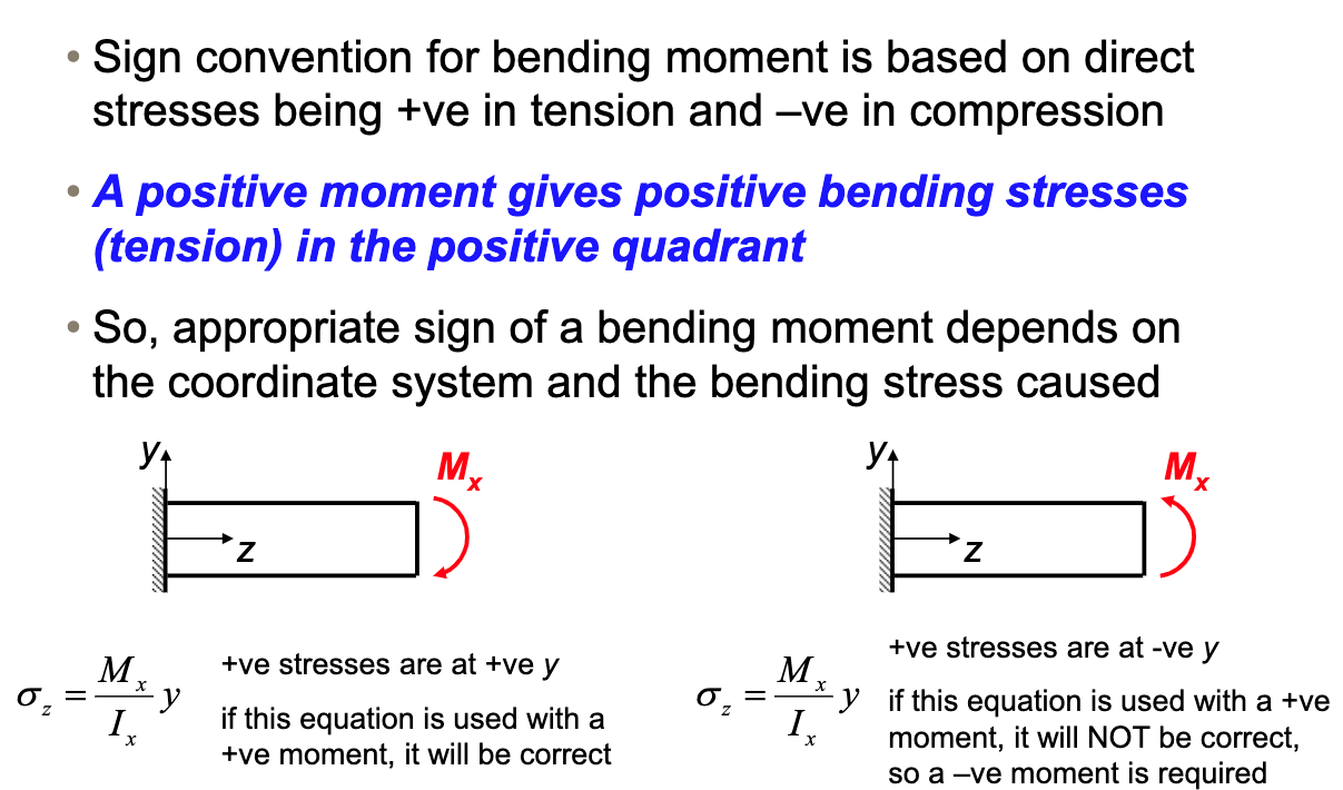
Bending Sign Convention
Thin Wall Assumptions
Equations
| Equation | Explanation | Variables |
|---|---|---|
| $I_{x} = {bd^3\over 12}$ | Second Moment of Inertia for a rectangle, measured from the x axis. | d is the direction perpendicular to the y axis. |
| $I_{x} = {b^3d\over 12}$ | Second Moment of Inertia for a rectangle, measured from the y axis. | b is the direction perpendicular to the x axis. |
Properties of Plane sections
- First Moment of Area (important for centroids)
- Second Moment of Area
- Rotation of Axes
- Parallel axis theorem
Stiffened Structures
- Consist of two structural elements, which can be assumed to perform seperate functions.
Shear
Shear flow
- Force on Length
Where,
T = applied torque, Ae = area enclose by cross-section (mid-line)